The EKG in a patient with a pacemaker
Editor-In-Chief: C. Michael Gibson, M.S., M.D. [1] Associate Editor-In-Chief: Cafer Zorkun, M.D., Ph.D. [2]
Pacemaker Code
- The first letter of the code indicates the chamber paced
- V - Ventricular
- A - Atrial
- D - Dual
- The second letter of the code indicates the chamber sensed
- V - Ventricular
- A - Atrial
- D - Dual
- 0 - none
- The third letter of the code indicates the mode of response
- I - Inhibited
- T - Triggered
- D - Double
- 0 - None
- VVI means that the ventricle is paced, the pacemaker senses the ventricle, and the pacemaker can be inhibited
- Now a fourth letter means that there is a telemetry function or programmability:
- P - Programmable
- M - Multiprogrammable
- C - Communicating
- 0 - None
- The fifth letter indicates special antitachycardia functions
- B - Bursts
- N - Normal rate competition
- S - Scanning
- E - External
Pacemaker Spikes
- Duration less than 2 msec, except when there is a long decay curve, and this decay curve can distort the QRS.
- Pacemakers with unipolar leads give much larger pacing spikes than those produced by bipolar leads
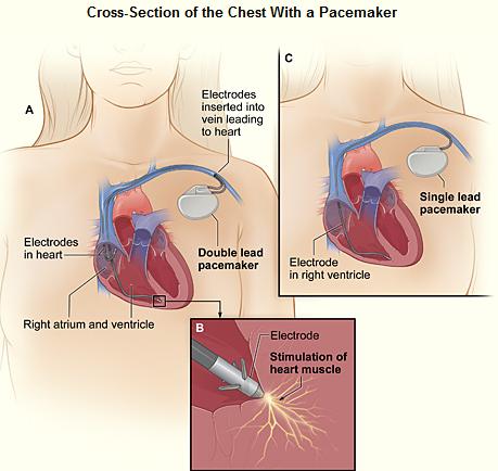
- In a bipolar lead, the negative electrode is located at the tip of the catheter and the positive electrode is 1 cm proximal to the tip. The current flows from the negative electrode to the positive electrode.
- In a unipolar lead, the active electrode, the cathode, is located at the tip of the catheter, and the indifferent electrode, the anode, is the exposed metal portion of the pulse generator. The electrical current flows form the tip of the catheter to the indifferent electrode through body tissue and fluid.
- Because of the greater distance between the two electrodes and therefore the bigger the dipole, the magnitude of the spike from unipolar pacemakers is larger.
- The longer distance between the electrodes makes is more vulnerable to extrinsic signal interference, such as electromagnetic and myopotential interference from skeletal muscles.
- The orientation of a unipolar spike will depend upon the location of the pulse generator since it is the positive pole.
Atrial Pacing
- If the site of stimulation is near the SA node in the RA, then the morphology of the P waves resembles that of sinus beats.
- If the site of stimulation is in the coronary sinus, then the morphology of the P waves is inverted in leads 2,3, and F.
Ventricular Pacing
- If the transvenous site of stimulation is in the RV, then a LBBB pattern appears. The sequence of activation is from the right to the left and from the apex to the base (i.e. a superior orientation, LAD). Unlike the usual LBBB, V6 may be predominantly negative.
- If the transvenous site of stimulation is at the inflow or the outflow tract of the RV, then the QRS axis is normal.
- If there is left ventricular epicardial-myocardial pacing there is RBBB.
Pacing-Induced T Wave Changes
- Inverted broad T waves associated with QT prolongation. They are seen most commonly in the inferior leads and in the left precordial leads. May resemble ischemic T waves.
Various types of pacemakers
- AOO (Atrial asynchronous):
- Also called a fixed-rate atrial pacemaker.
- No sensing function.
- A lead is connected to the RA, which it paces at a preset rate, regardless of the patient's own heart rate or rhythm.
- Requires an intact AV conduction system.
- Rarely used.
- AAI, and AAT (Atrial demand pacemakers):
- In AAI pacemakers, if there is spontaneous atrial activity at a rate greater than (or the PP interval is less than) a predetermined level, then no stimulus is delivered.
- In AAT pacemakers, the pacer senses the atrial impulse and stimulates the atrium when the atrial rate falls below a certain level, but it also delivers stimuli when it senses native P waves.
- Also rarely used.
- VOO (Ventricular asynchronous):
- Also called fixed-rate ventricular pacemakers.
- Delivers stimuli at a constant rate regardless of the patient's own heart rate or rhythm.
- Competes with the patient's native QRS, if the latter are present.
- Each stimulus is followed by a QRS complex unless the stimulus occurs during the ventricular refractory period.
- Fusion beats may be seen, part of the ventricle depolarized by the patient's own impulse and part by the artificial pacemaker.
- There is a risk that the spike may fall during the vulnerable period, resulting in ventricular fibrillation.
- Risk is low in most patients but increases in the presence of ischemia, electrolyte imbalance, or drug toxicity.
- A magnet converts demand pacemakers to this mode of pacing.
- VVI or VVT (Ventricular Demand Pacemakers):
- Most popular in use, particularly VVI.
- The pacemaker generates impulses whenever the patient's own ventricular rate falls below a predetermined level. The stimulus is suppressed of the patient's own ventricular rate is above this level.
- Pacing rate is usually 72 beats/minute.
- The interval from a native complex to that of a pacemaker spike is called the escape interval. This interval may not be the same as the pace interval (the spike-to-spike interval) and is usually much longer because depending on the site of origin of the spontaneous impulse, its potential may not be sensed by the pacemaker until the later portion of the depolarization.
- In some pacemakers, the escape interval is deliberately set longer than the pacing interval a feature which is known as hysteresis.
- Fusion beats may occur.
- Occasionally there are pseudofusion beats in which case the pacemaker spike falls on the spontaneous beat. The pacemaker spike does not cause depolarization, and other than the superimposed spike, it has the same morphology as a pure spontaneous beat. occurs when the pacemaker fires during the absolute refractory period of the heart.
- Pseudofusion beats are more likely to be seen in those patients with an IVCD or PVCs.
- May be seen in patients with a RV pacemaker and left-sided PVCs or an LV pacemaker and a right-sided PVC.
- VVI pacemaker in the magnet mode:
- Converts the pacemaker to a fixed-rate mode.
- A significant decrease in the pacing rate indicates a decrease in the pacemaker's battery voltage.
- Rate-responsive pacemakers:
- Increase the pacing rate in response to physiologic demands.
- Methods of detecting the need for an increased rate include a piezoelectric crystal that detects vibration generated by body motion, an RV body temperature monitor, the measurement of the QT interval, mixed venous O2 saturation.
- VVT (Ventricular triggered pacemakers):
- Functions similarly to the inhibited type (VVI) of pacemaker in that it delivers a stimulus at a preset interval if no spontaneous ventricular depolarization is detected.
- It differs from the ventricular inhibited pacemakers by also delivering a stimulus immediately after a spontaneous QRS is sensed.
- When there is a spontaneous ventricular complex, the pacing spike comes shortly after the QRS.
- In the paced beats, the stimulus spike initiates rather than falls on the QRS complexes.
- Were originally developed to avoid the potential problem of pacemaker inhibition by extracardiac signals such as those that originated from skeletal muscles or radio transmitters. Modern circuitry has reduced the likelihood of such interferences.
- Because of
- power drain
- distortion of the native QRS
- This mode is infrequently used.
Pacemaker Malfunction Detection by Routine EKG
- With a demand pacemaker there may be a loss of either sensing or capturing
- Loss of sensing occurs before loss of pacing
- Sources of malfunction:
- pulse generator
- lead
- junction of the electrode and the cardiac tissue
Sensing Malfunction
- Undersensing:
- When it has lost its ability to sense it functions as a fixed-rate asynchronous pacemaker.
- Sometimes exercise will increase the native heart rate and expose a failure to sense.
- May not always be due to pulse generator malfunction. It may be due to scar tissue, inadequate myocardial or endocardial contact, poor orientation of a bipolar electrode, or inappropriate programming of amplifier sensitivity in a newly placed pacemaker.
- Late sensing loss may be due to acute MI, growth of insulating tissue around the electrode, or myocardial perforation with the electrode migrating to a poor signal area. Broken leads or wire insulation are now uncommon causes as the quality of the wires has improved.
- Oversensing:
- Uncommon to oversense physiologic intracardiac voltage.
- Occasionally very tall p waves or t waves may be mistaken for qrs complexes.
- Myopectoral inhibition may occur when the pectoralis muscle inhibits the pacer.
- Radar, TV, radiotransmitters and electrocautery may inhibit the pacemaker.
- Microwave and weapon detector equipment no longer cause a problem in modern equipment.
- DC countershock and XRT may damage pulse generators.
Pacing Malfunction
- Can only be recognized of the patient's rate is slow enough to permit pacer spikes.
- If the patient's rate is too rapid, then a magnet can be applied to convert the pacer to a fixed-rate mode.
- A change in the spike to spike interval of more than 10 msec may indicate early battery depletion. Such a change in the rate is difficult to determine from the routine EKG, and a change of 1 to 2 beats per minute may be due to a change in the paper speed.
- Generally, a slowing of more than 4 beats per minute is an indication of battery depletion.
- Some pacemakers now allow the detection of a reduction in the pulse width or pulse amplitude of the spike.
- Myocardial perforation may be responsible for pacing failure.
- RV endocardial leads may perforate either the interventricular septum or more commonly the free wall of the RV, ECG would then change from a LBBB to a RBBB.
VAT (Atrial Synchronous Pacemakers)
- This is a ventricular stimulating pacemaker with its pacing rate dependent on the atrial rate.
- Rarely used.
- If the atrial potential is inadequate or absent within a preset interval, then the pacemaker becomes an asynchronous ventricular pacemaker.
- If the atrial rate becomes too rapid then the pacer is programmed to produce 2:1, 3:1 or 4:1 block.
VDD (Atrial Synchronous Ventricular Inhibited Pacemakers)
- It senses and paces the ventricle.
- It has been refined by the addition of ventricular sensing and provides for ventricular pacing during sinus bradycardia.
DVI (Atrioventricular Sequential Pacemakers)
- Dual-chamber pacemaker that paces both the atrium and the ventricle and senses only the ventricle.
- If conducted supraventricular beats occur at a rate above a preset level, all activities of the pacemaker are suppressed.
- If no ventricular potential is sensed by the ventricular electrode at a predetermined interval, atrial pacing occurs.
- Subsequent ventricular pacing activity depends on the type of the AV sequential pacemaker, committed or uncommitted.
- uncommitted: ventricular pacing is inhibited by the native QRS interval if the spontaneous AV conduction time is shorter than the programmed pacemaker AV interval.
- committed: ventricular pacing occurs at the programmed AV interval regardless of whether there is spontaneous AV conduction.
- In both types, the pacemaker restores normal AV sequence only when the native atrial rate is slower than the pacemaker's automatic rate.
DDD (Atrioventricular Universal Pacemakers)
- The most common dual chamber device implanted today.
- Senses both the atrium and the ventricle.
- It may be inhibited or triggered to pace the atrium or ventricle or both according to the programmed rate limits and AV interval.
- The rate is often programmed to be 60 beats/min, the upper rate is 150 beats/min and the AV interval is 200 msec.
- If the rate is faster than 60 beats/min (if a P wave appears is less than 800 msec from the preceding QRS) and the AV conduction time is less than 200 msec (the programmed intervals) then no pacing stimulus is seen.
- There are built in features to prevent pacemaker-induced arrhythmias so that no ventricular stimulus is delivered in less than 400 msec from the preceding QRS interval. This is the same as an upper rate limit of 150 beats/min.
- If a PVC is sensed less than 800 msec after the preceding QRS, both atrial and ventricular pacing is inhibited. The atrial and the ventricular response is reset by the PVC.
- Application of a magnet results in DOO pacing (asynchronous pacing in both the atria and the ventricles).
DDD Pacemaker Related Tachycardias
- Wenckebach pacemaker response
- Occurs when the atrial rate is faster than the programmed DDD pacemaker upper rate limit.
- In this situation, the atrial pacemaker is inhibited.
- The ventricle does not necessarily fire at the preset AV interval, it will wait until the upper rate limit (the upper VV interval) is reached.
- Therefore there is prolongation of the P to V interval , the degree to which is proportional to the preceding VP interval.
- Pacemaker Circus Movement Tachycardia
- Also called endless loop tachycardia
- The cause is retrograde P waves.
- Such a retrograde P wave is sensed by the atrial component of the pacemaker, which in turn triggers the delivery of a ventricular stimulus, resulting in a paced QRS complex with retrograde atrial capture.
- The rate is limited by the upper rate of the pacemaker.
- Lengthening the atrial refractory period of the pacemaker may decrease the incidence of, but does not eliminate this potential complication.
Hysteresis, Fallback Response, Cross Talk
- With regard to atrial hysteresis, there are two AV intervals. The AV interval of a sensed atrial event is shorter than that which follows an atrial stimulus.
- The reason for this is to make the AV intervals the same in actuality to maintain the hemodynamic benefit of the atrial contraction.
- The reason that the interval following a sensed atrial beat is that there is a time delay between when the pacemaker senses the atrial activity. When atrial activity is sensed, atrial contraction is likely to have begun.
- Rate hysteresis is present when the pacemaker escape interval is longer than the pacing interval. This allows the patient's own sinus rhythm, which is more physiological, to be maintained at a lower rate than the pacing rate.
- In patients who cannot tolerate a sustained upper rate, the fallback response mechanism returns the ventricular response rate to more tolerable levels. AV synchrony may not be maintained during the fallback response.
- Cross talk refers to the phenomenon whereby the ventricular channel senses the atrial impulse and is thereby inhibited. To overcome this, the ventricular sensing circuit is turned off shortly after the atrial stimulus.
Pacemaker Syndrome
- Refers to dizziness, near syncope, and fatigue even though there is no pacemaker malfunction. This syndrome is the result of unfavorable hemodynamic consequences of AV asynchrony.
- The incidence is higher in patients with VA conduction.
EKG Findings
-
 Ventricular paced rhythm shows ventricular pacemaker spikes
 -
 DDD type pace rhythm

-
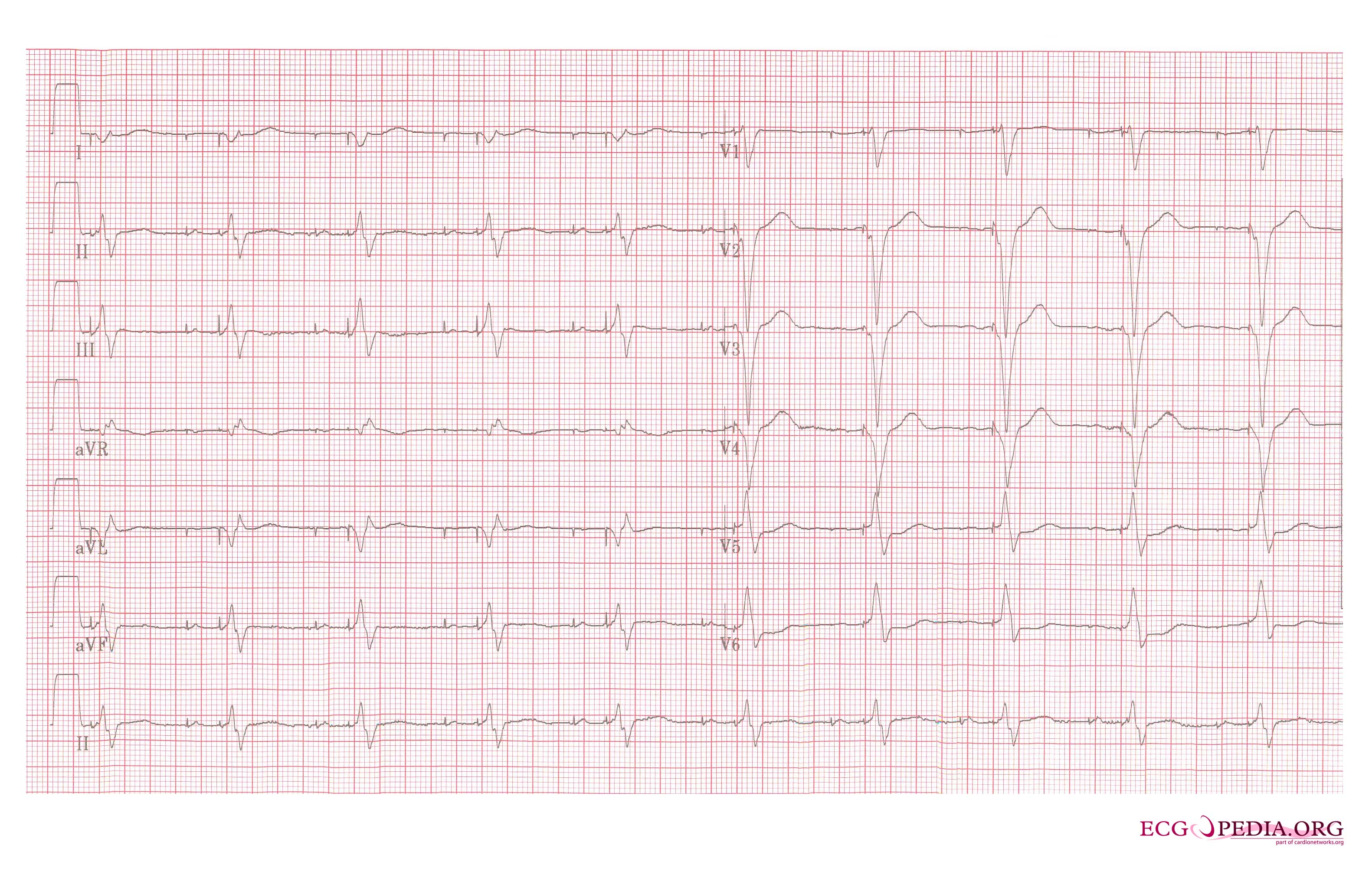
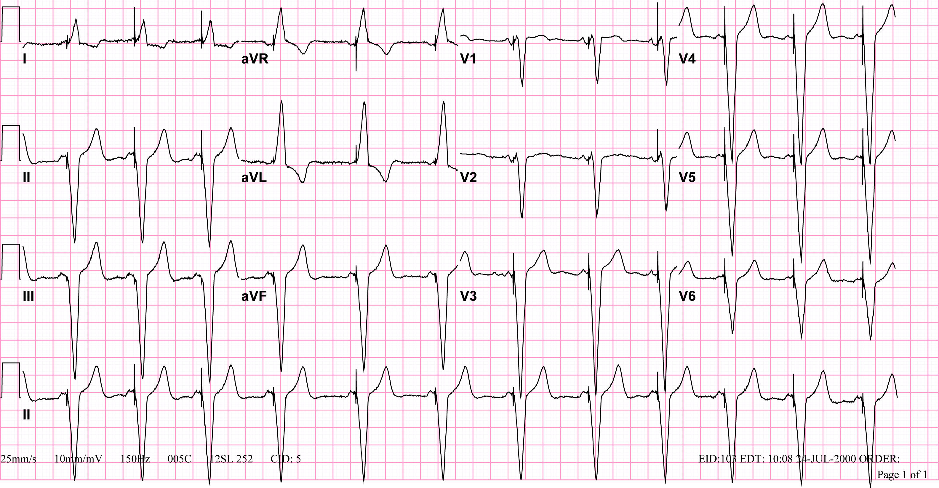 VVI pacemaker rhythm. Note the LBBB morphology with left axis deviation indicating the pacing lead in the right ventricular apex.
 -
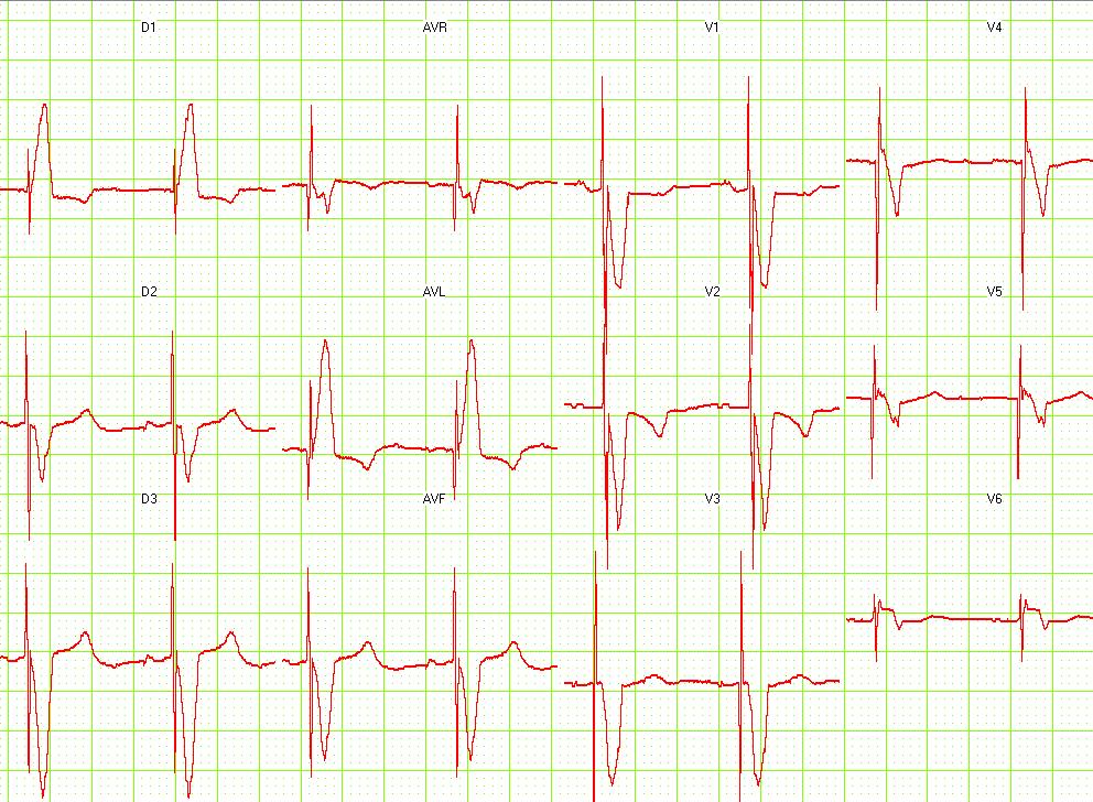 Ventricular paced rhythm


-
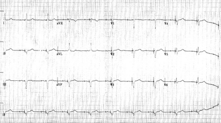 12 lead EKG: Dual chamber pacemaker
 -


This is a rhythm strip recorded from a man attending the pacemaker follow-up clinic. The Patient had been implanted with a dual chamber pacemaker one month before. The pacer was programed to VVI mode and AAI mode and ECG recordings were made.

This is a rhythm strip recorded from a man attending the pacemaker follow-up clinic. The Patient had been implanted with a ventricular pacemaker one week before. In about the middle of the tracing a magnet was placed over the pacemaker.

This is an EKG rhythm from a patient with a Medtronic model 8081 Premier single chamber pacemaker. The patient is a 65 year old man who had a history of blackouts while sitting. During the episodes his wife described him as becoming limp and white. His electrocardiogram showed a left bundle branch block with a normal pr interval. This conduction abnormality had been present for at least 16 years.

This is a ladder diagram and surface tracing from a patient with a dual chamber pacemaker. The pacer is pacing the atrium (star) and sensing the ventricle. Note the refractory periods (boxes) of the atrium the ventricle and the post ventricular atrial refractory period.

Shown below is an EKG where the pacer should have started to pace the atrium when set at 100/min. The failure to do so suggests that the pacing system is non-functional (depleted pacemaker battery, broken lead etc.) or that the pacer is sensing an atrial rhythm faster than 100/min.

Sources
Copyleft images obtained courtesy of ECGpedia, http://en.ecgpedia.org/index.php?title=Special:NewFiles&dir=prev&offset=20080806182927&limit=500
References
- Adapted in part from Chou's Electrocardiography in Clinical Practice Third Edition, pp. 540 - 566.