Coronary catheterization: Difference between revisions
No edit summary |
|||
| Line 203: | Line 203: | ||
The bifurcation of the distal RCA and rPDA is best seen in the AP 0 Cranial 30 view with a small breath in. | The bifurcation of the distal RCA and rPDA is best seen in the AP 0 Cranial 30 view with a small breath in. | ||
{{#ev:youtube|zTwLSi0-b94}} | |||
==ACC-AHA CHARACTERISTICS OF TYPE A, B, AND C CORONARY LESIONS == | ==ACC-AHA CHARACTERISTICS OF TYPE A, B, AND C CORONARY LESIONS == | ||
Revision as of 16:10, 2 May 2012
| Coronary catheterization | |
 | |
|---|---|
| Coronary catheterization:Left coronary artery injection |
Editor-In-Chief: C. Michael Gibson, M.S., M.D. [1]
Overview
Coronary catheterization is an invasive procedure to access the coronary circulation and blood filled chambers of the heart using a catheter. It is performed for both diagnostic and interventional (treatment) purposes. Coronary catheterization is one of the several cardiology diagnostic tests and procedures. Specifically, coronary catheterization is a visually interpreted test performed to recognize occlusion, stenosis, restenosis, thrombosis or aneurysmal enlargement the coronary artery lumens, heart chamber size, heart muscle contraction performance and some aspects of heart valve function. Important internal heart and lung blood pressures, not measurable from outside the body, can be accurately measured during the test. The relevant problems that the test deals with most commonly occur as a result of advanced atherosclerosis, atheroma activity within the wall of the coronary arteries. Less frequently, other issues, valvular, heart muscle or arrhythmia issues are the primary focus of the test.[1] [2] [3] [4]
Coronary artery luminal narrowing reduces the flow reserve for oxygenated blood to the heart, typically producing intermittent angina if very advanced; luminal occlusion usually produces a heart attack. However, it has been increasingly recognized, since the late 1980s, that coronary catheterization does not allow the recognition of the presence or absence of coronary atherosclerosis itself, only significant luminal changes which have occurred as a result of end stage complications of the atherosclerotic process. See IVUS and atheroma for a better understanding of this issue.
History
Coronary catheterization was introduced in 1929 when the German physician Dr. Werner Forssmann inserted a plastic tube in his cubital vein and guided it to the right chamber of the heart. He took an x-ray to prove his success and published it on November 5 1929 with the title "Über die Sondierung des rechten Herzens" (About probing of the right heart). The coronary catheterization of the left heart was introduced in the late 1950s, and the first report appeared in 1960 (Sones & Shirey). The first case of coronary catheterization was serendipitous: Sones, a pediatric cardiologist at the Cleveland Clinic, accidentally injected radiocontrast in the coronary artery instead of the left ventricle. Although the patient had a reversible cardiac arrest, Sones and Shirey developed the procedure further, and are credited with the discovery (Connolly 2002); they published a series of 1,000 patients in 1966 (Proudfit et al).
Since the late 1970s, building on the pioneering work of Charles Dotter in 1964 and especially Andreas Gruentzig starting in 1977, coronary catheterization has been extended to more important uses: (a) the performance of less invasive physical treatment for angina and some of the complications of severe atherosclerosis, (b) treating heart attacks before complete damage has occurred and (c) research for better understanding of the pathology of coronary artery disease and atherosclerosis.
Patient participation
The patient being examined or treated is usually awake during coronary catheterization, ideally with only local anaesthesia such as lidocaine and minimal general sedation, throughout the procedure. Performing the procedure with the patient awake is safer as the patient can immediately report any discomfort or problems and thereby facilitate rapid correction of any undesirable events. Medical monitors never tell the whole story; how the patient feels is often a most reliable indicator of procedural safety.
In the early 1960s, cardiac catheterization frequently took several hours and involved significant complications for as many as 2-3% of patients. With multiple incremental improvements over time, simple coronary catheterization examinations are now commonly done in as little as 5-8 minutes, with multiple views, far better images and significant complication rates typically in 0.1% range. However, though the imaging portion of the examination is often brief, because of setup and safety issues, the patient is often in the lab for 20 to 45 minutes. Any of multiple technical difficulties, while not endangering the patient (indeed added to protect the patient's interests) can significantly increase the examination time.
Contraindications
There are no absolute contraindications to cardiac catheterization. Relative contraindications include:
- Coagulopathy
- Decompensated congestive heart failure
- Uncontrolled Hypertension
- CVA
- Refractory Arrhythmia
- GI Hemorrhage
- Pregnancy
- Inability for patient cooperation
- Active infection
- Renal Failure
- Contrast medium allergy
Complications
The overall risk of major complications with left heart catheterization is 1-2%. This include death, bleeding, vascular complications, AMI, CVA, and contrast reaction.
Factors increasing patient risk include:
- Age
- Left main or 3 vessel coronary artery disease
- Decompensated heart failure
- Severe aortic stenosis
- Diabetes mellitus
- Renal failure
- Prior CVA
Equipment
Coronary catheterization is performed in a cardiac catheterization lab, usually located within a hospital. With current designs, the patient must lay relatively flat on a narrow, minimally padded, radiolucent (transparent to X-Ray) table. The X-Ray source and imaging camera equipment are on opposite sides of the patient's chest and freely move, under motorized control, around the patient's chest so images can be taken quickly from multiple angles. More advanced equipment, termed a bi-plane cath lab, uses two sets of X-Ray source and imaging cameras, each free to move independently, which allows two sets of images to be taken with each injection of radiocontrast agent.
The equipment and installation setup to perform such testing typically represents a capital expenditure of 2 to 5 million U.S. 2004 dollars, sometimes more, partially repeated every few years.
Diagnostic procedures

During coronary catheterization (often referred to as a cath by physicians), blood pressures are recorded and X-Ray motion picture shadow-grams of the blood inside the coronary arteries are recorded. In order to create the X-ray pictures, a physician guides a small tube-like device called a catheter, typically ~2.0 mm (6-French) in diameter, through the large arteries of the body until the tip is just within the opening of one of the coronary arteries. By design, the catheter is smaller than the lumen of the artery it is placed in; internal/intraarterial blood pressures are monitored through the catheter to verify that the catheter does not block blood flow.
The catheter is itself designed to be radiodense for visibility and it allows a clear, watery, blood compatible radiocontrast agent, commonly called an X-ray dye, to be selectively injected and mixed with the blood flowing within the artery. Typically 3-8 cc of the radiocontrast agent is injected for each image to make the blood flow visible for about 3-5 seconds as the radiocontrast agent is rapidly washed away into the coronary capillaries and then coronary veins. Without the X-ray dye injection, the blood and surrounding heart tissues appear, on X-ray, as only a mildly-shape-changing, otherwise uniform water density mass; no details of the blood and internal organ structure are discernible. The radiocontrast within the blood allows visualization of the blood flow within the arteries or heart chambers, depending on where it is injected.
If atheroma, or clots, are protruding into the lumen, producing narrowing, the narrowing is seen as either a narrowing or increased haziness within the X-ray shadow images of the blood/dye column within that portion of the artery; this is as compared to adjacent, presumed healthier, less stenotic areas. See the single frame illustration of an coronary angiogram image on the angioplasty page.
For guidance regarding catheter positions during the examination, the physician mostly relies on detailed knowledge of internal anatomy, guide wire and catheter behavior and intermittently, briefly uses fluoroscopy and a low X-Ray dose to visualize when needed. This is done without saving recordings of these brief looks. When the physician is ready to record diagnostic views, which are saved and can be more carefully scrutinized later, he activates the equipment to apply a significantly higher X-Ray dose, termed cine, in order to create better quality motion picture images, having sharper radiodensity contrast, typically at 30 frames per second. The physician controls both the contrast injection, fluoroscopy and cine application timing so as to minimize the total amount of radiocontrast injected and times the X-Ray to the injection so as to minimize the total amount of X-Ray used. Doses of radiocontrast agents and X-Ray exposure times are routinely recorded in an effort to maximize safety.
Though not the focus of the test, calcification within the artery walls, located in the outer edges of atheroma within the artery walls, is sometimes recognizable on fluoroscopy (without contrast injection) as radiodense halo rings partially encircling, and separated from the blood filled lumen by the interceding radiolucent atheroma tissue and endothelial lining. Calcification, even though usually present, is usually only visible when quite advanced and calcified sections of the artery wall happen to be viewed on end tangentially through multiple rings of calcification, so as to create enough radiodensity to be visible on fluoroscopy.
Technique
Access
Common Femoral Arterial Access is the most common arterial access for performing left heart catheterization. The original catheterization procedure was performed via brachial access. This site is still commonly used in patients with lower extremity peripheral access issues. Arm access also facilitates internal mammary access, especially in patients with tortuous innominant or subclavian arteries. Radial artery access is also used commonly in some practice settings. Before radial access is performed, competence of the radial artery arch should be assessed with the Allen Test. Use of pulse oximetry can facilitate interpretation of the test.
Anatomic landmarks are used to identify the correct site of arterial puncture. For the femoral artery access, the femoral head provides the best visible landmark. Arterial puncture at this site remains below the inguinal ligament, is generally above the bifurcation of the superficial femoral and deep femoral arteries, and allows for hemostasis. It is recommended that this site should be observed under fluoroscopy in any patient prior to access. In obese patients the inguinal skin crease is generally too low (see figure).

<youtube v=Z2fWgIa3vzc/>
After the administration of subcutaneous anesthetic, an 18G Cook needle is used to puncture the the front wall of the artery. This technique is known as the modified Seldinger technique and prevents posterior arterial bleeding or venous communication from the puncture. Complications from arterial access include arterial dissection, AV fistula formation, retroperitoneal hemorrhage, and pseudoanuerysm formation.
{{#ev:googlevideo|-706127292516153805&hl=en}}
{{#ev:googlevideo|7797566665521374524</googlevideo>=en}}
{{#ev:googlevideo|-4335144279066692747&hl=en}}
{{#ev:googlevideo|959006640183044826&hl=en}}
Once access is obtained, the Cook needle is steadied while the artery is accessed with a wire through the lumen of the Cook needle. The Cook needle is then removed and a sheath is inserted into the artery. Under floroscopy, catheters are then introduced using an 0.35 J-tipped guide wire into the aortic root. The catheters are then attached to a 3 way manifold. Manifold used allows for continuous pressure monitoring, saline flush instillation, and contrast administration through the catheter tip.
Catheters
Catheter selection for a routine left heart catheterization is generally straight forward.
Most often, Judkins catheter types are most routinely used. For engagement of the left main coronary artery, A Judkins Left size 4 (JL4) catheter generally will generally engaged the left coronary artery in most patients with relative ease. Increasing catheter size (JL5) for tall patients or patients with dilated aorta or decreasing size (JL 3.5) in small patients is sometimes required. Engagement of the LMT is usually most straightforward in the LAO projection. For extremely dilated roots or anomalous arteries other catheters such as Amplatz catheters can be used. For the right coronary artery, a Judkins Right Size 4 (JR4) is most often used. The right coronary artery is engaged in the LAO projection. Usually slow clockwise rotation of the JR4 in the aortic root will engage the ostium of the RCA. Specialized catheters are available to engage anomalous origins of coronary arteries and saphenous and internal mammary artery bypass grafts.
Once the artery is engaged is is important to examine the pressure wave form. Normally, the waveform should mimic aortic root pressure. Dampening or ventricularization of the pressure waveform may indicate over engagement of the catheter or significant vessel stenosis. Extreme care should be taken before instillation of contrast medium without normal pressure waveforms.
Basics of Coronary anatomy
The tricuspid aortic valve gives rise to 3 cusp or sinuses in the aortic root. The left coronary and right coronary cusp give rise to their respective coronary arteries while the non-coronary cusp which arises from the posterior root usually does not give rise to a coronary artery.
The major epicardial vessels supplying the myocardium are the left main coronary artery that divides into the Left anterior descending artery and Left Circumflex Artery, and the Right Coronary artery. These arteries lie on the epicardial surface and supply smaller branch vessels that eventually give rise to the microvascular network supplying the myocardium.
Coronary dominance is based on the vessel that gives rise to the posterior descending artery (PDA) which travels in the posterior interventricular groove and supplies the Atrio-ventricular node (AV node). This vessel, which can be recognized by the presence of septal perforating branches, arises from the RCA in 80% of the population and the LCx in 10% of the population. Co-Dominance of the arterial circulation is found in 10% of the population where the posterior interventricular artery is formed by both the RCA and LCx.
The Left main coronary artery or Left Main Trunk (LMT) originates from the left coronary cusp and bifurcates to give rise to the Left anterior descending (LAD) and Left Circumflex (LCx) coronary arteries. Occasionally, a third branch vessel, the Ramus Intermedius (RI) arises from the LMT. The LMT varies in length in many patients and in a small number of patients, the two major branch vessels arise from separate origins.
The Left anterior descending coronary artery (LAD) provides blood supply to the anterior wall of the left ventricle. As it courses through the anterior intraventricular groove it provides multiple septal branches to the interventricular septum and diagonal branches to the anterior lateral wall. The LAD then courses to the ventricular apex and in some patients wraps around the apex to supply a small amount of the posterior apex.
The Left Circumflex coronary artery (LCx) courses around the lateral or left atrio-ventricular groove and gives rise to multiple marginal or lateral branches. The branches are termed obtuse marginal (OM) or lateral branches depending on institutional preference. OM branches are sequentially numbered (OM1, OM2 etc…) while Lateral branches are termed based on the segment of the lateral wall they supply (High Lateral, Lateral, Posterior Lateral). As the LCx courses the AV groove it also gives rise to several atrial branches, and occasionally the sino-atrial branch (40% of the population).
The right coronary artery (RCA) arises from the right coronary cusp. This vessel follows the right AV groove and provides branches to the right ventricle. The most proximal branches of the RCA are the conus-branch which supplies the right ventricular outflow tract and a branch that supplies the sino-atrial (SA) node (60% of patients). The RCA then courses through the interventricular and gives rise to marginal branches and branches to the atrium. [Manipulation of the coronary arteries in 3-dimensions via spacial reconstructions of the coronary arteries is helpful in interpreting coronary angiographic images.
Standard Angiographic Views
For the beginner angiographer the anatomic landmarks formed by the spine, catheter and diaphragm provide information to discern which tomographic view from which the image is obtained. In the LAO view (figure 1) the catheter and spine are seen on the right side of the image, while in the RAO (figure 2) they are found on the right. PA imaging (figure 3) places these landmarks in the center of the image. Cranial angulation can usually be distinguished from caudal angulation by the presence of the diaphragm. For cranial imaging, the patient should be asked to inspire to remove the diaphragmatic shadow from the image.
 |
 |
 |
Left Coronary Artery
The left main coronary artery gives rise to the left anterior descending artery and the left circumflex coronary artery. Complete visualization of these arteries and their branches requires care and rigor to ensure complete anatomical documentation. Often bifurcations and vessel foreshortening and overlap cause errors in stenosis estimation. There are no steadfast rules in which tomographic views are most useful. Generally, for circumflex and proximal epicardial visualization the caudal views are most useful. For LAD and LAD/diagonal bifurcation visualization the cranial views are most useful. Overall, if there is not a significant limitation on contrast utilization, standard 'around the world' angiography using a selection of the following angiographic views will document left coronary anatomy.
RAO 20 - Caudal 20
 |
6247188073495527363&hl=en}} |
AP 0 - Caudal 30
 |
2929371918192985322&hl=en}} |
LAO 50 - Caudal 30
 |
7433964206205091552&hl=en}} |
LAO 50 - Cranial 30
 |
5432992955366236190&hl=en}} |
AP 0 - Cranial 40
 |
7585919423573443431&hl=en}} |
Right Coronary Artery
The Right coronary artery is engaged in the LAO position.
Initial angiographic imaging of the RCA in this view (LAO 30) gives the best view of significant ostial and proximal RCA disease.
{{#ev:googlevideo|5500067896904451884&hl=en}}
The mid RCA is best visualized in the straight RAO 30 position.
{{#ev:googlevideo|-4058224532097737773&hl=en}}
The bifurcation of the distal RCA and rPDA is best seen in the AP 0 Cranial 30 view with a small breath in.
{{#ev:youtube|zTwLSi0-b94}}
ACC-AHA CHARACTERISTICS OF TYPE A, B, AND C CORONARY LESIONS
Type A Lesions (High Success [> 85%]; Low Risk)
- Discrete (< 10 mm)
- Little or no calcium
- Concentric
- Less than totally occlusive
- Readily accessible
- Not ostial in location
- Nonangulated segment (< 45 degrees)
- No major side branch involvement
- Smooth contour
- Absence of thrombus
Type B Lesions (Moderate Success [60%–85%]; Moderate Risk)
- Tubular (10–20 mm length)
- Moderate to heavy calcification
- Eccentric
- Total occlusions < 3 months old
- Moderate tortuosity of proximal segment
- Ostial in location
- Moderately angulated (45-90 degrees)
- Bifurcation lesion requiring double guidewire
- Irregular contour
- Some thrombus present
Type C Lesions (Low Success [< 60%]; High Risk)
- Diffuse (> 20 mm length)
- Total occlusion > 3 months old
- Excessive tortuosity of proximal segment
- Inability to protect major side branches
- Extremely angulated segment (> 90 degrees)
- Degenerated vein grafts with friable lesions
Risk Assessment Using Specific Lesion Morphologic Criteria
Despite the value of risk scores in estimating aggregate procedural risk, there are several limitations of these criteria as applied to individual patients. Identification of lesion characteristics, such as eccentricity, irregularity, angulation, and tortousity, is limited by substantial inter-observer variability. Agreement with ACC/AHA classification was noted in only 58% of lesions in one series, with disagreement by two classification grades noted in nearly 10% of lesions.
Accordingly, rather than a composite score, description of individual morphologic features may be more predictive of early and late outcome following PCI. Some ACC/AHA morphologic features are associated with a complicated procedure (e.g., thrombus, saphenous vein graft [SVG] degeneration, and angulated segments), whereas others are associated with an unsuccessful but uncomplicated procedure (e.g., chronic total occlusions or diffuse disease). As an alternative to providing a composite lesion complexity score, estimation of procedural risk based on the presence of one or more specific adverse morphologic features may be more useful.
Definitions of Preprocedural Lesion Morphology
Feature: Definition
- Eccentricity: Stenosis that is noted to have one of its luminal edges in the outer one quarter of the apparently normal lumen
- Irregularity: Characterized by lesion ulceration, intimal flap, aneurysm, or “sawtooth” pattern
- Ulceration: Lesion with a small crater consisting of a discrete luminal widening in the area of the stenosis is noted, provided it does not extend beyond the normal arterial lumen
- Intimal flap: A mobile, radiolucent extension of the vessel wall into the arterial lumen
- Aneurysmal dilation: Segment of arterial dilation larger than the dimensions of the normal arterial segment
- “Sawtooth pattern”: Multiple, sequential stenosis irregularities
- Lesion length: Measured “shoulder-to-shoulder” in an unforeshortened view
- Discrete Lesion length < 10 mm
- Tubular Lesion length 10–20 mm
- Diffuse Lesion length ≥ 20 mm
- Ostial location: Origin of the lesion within 3 mm of the vessel origin
- Lesion angulation: Vessel angle formed by the centerline through the lumen proximal to the stenosis and extending beyond it and a second centerline in the straight portion of the artery distal to the stenosis
- Moderate: Lesion angulation ≥ 45 degrees
- Severe: Lesion angulation ≥ 90 degrees
- Bifurcation stenosis: Present if a medium or large branch (>1.5 mm) originates within the stenosis and if the side branch is completely surrounded by stenotic portions of the lesion to be dilated
- Lesion accessibility (proximal tortuosity)
- Moderate tortuosity: Lesion is distal to two bends ≥ 75 degrees
- Severe tortuosity: Lesion is distal to three bends ≥ 75 degrees
- Degenerated saphenous vein graft: Graft characterized by luminal irregularities or ectasia comprising > 50% of the graft length
- Calcification: Readily apparent densities noted within the apparent vascular wall at the site of the stenosis
- Moderate: Densities noted only with cardiac motion prior to contrast injection
- Severe: Radiopacities noted without cardiac motion prior to contrast injection
- Total occlusion: TIMI 0 or 1 flow
- Thrombus: Discrete, intraluminal filling defect is noted with defined borders and is largely separated from the adjacent wall; contrast staining may or may not be present
Quantitative Angiography
While “on-line” quantitative angiographic is somewhat cumbersome to use in the catheterization laboratory, “off-line” quantitative angiography has proven invaluable for research investigation in determining the effect of new drugs and devices on lumen dimensions early and late after percutaneous coronary interventions.
Notably, for clinical decision making in intermediate lesions, neither trained visual estimates or on-line quanitative angiography are substitutes for precise physiologic measurements of stenosis severity, such as fractional flow reserve or coronary Doppler measurements.
Computer-Assisted Quantitative Angiography
Quantitative coronary angiography was initiated nearly 30 years ago by Brown and colleagues who magnified 35-mm cineangiograms obtained from orthogonal projections and hand traced the arterial edges on a large screen. After computer-assisted correction for pincushion distortion, the tracings were digitized and the orthogonal projections were combined to form a three-dimensional representation of the arterial segment, assuming an elliptical geometry. While the accuracy and precision were enhanced compared with visual methods, the time needed for image processing limited its clinical use.
Several automated edge-detection algorithms were then developed and applied to directly acquired digital images or to 35-mm cinefilm digitized using a cine-video converter. Subsequent interations of these first degeneration devices have utilized enhanced microprocessing speed and digital image acquisition to render the end-user interface more flexible and substantially shortened the time required for image analysis.
Quantitative coronary angiography is divided into several distinct processes, including film digitization (when applicable), image calibration, and arterial contour detection. For processing 35-mm cinefilm, a cine-video converter is used to digitize images into a 512 × 512 (or larger) × 8-bit pixel matrix. Optical, or less preferred digital, magnification results in an effective pixel matrix up to 2458 × 2458.
Image Calibration
For estimation of absolute coronary dimensions, the diagnostic or guiding catheter is generally used as the scaling device. In general, a nontapered segment of the catheter is selected, and a centerline through the catheter is drawn. Linear density profiles are then constructed perpendicular to the catheter centerline, and a weighted average of the first and second derivative function is used to define the catheter edge points. Individual edge points are then connected using an automated algorithm, outliers are discarded, and the edges are smoothed. The diameter of the catheter is then used to obtain a calibration factor, expressed in millimeters per pixel. The injection catheter dimensions may be influenced by whether contrast or saline is imaged within the catheter tip, and by the type of material used in catheter construction. As the high-flow injection catheters have been developed, more quantitative angiographic systems using contrast-filled injection catheters for image calibration.
Quantitative Coronary Analysis
The automated algorithm is then applied to a selected arterial segment, and absolute coronary dimensions are obtained from the minimal lumen diameter (MLD) reference diameter, and from these, the percent diameter stenoses are derived. For most angiographic systems, interobserver variabilities are 3.1% for diameter stenosis and 0.10 to 0.18 mm for MLD for cineangiographic readings; variabilities are slightly higher (< 0.25 mm) for repeated analyses of the digital angiograms due the the slightly lower resolution compared with cineangiography. The two most commonly used quantitative angiographic systems are described below:
- CARDIOVASCULAR ANGIOGRAPHY ANALYSIS SYSTEM. CAAS (Pie Data Medical B.V., Maastricht, The Netherlands) is a quantitative angiographic system developed for off-line cineangiographic analysis. The edge-detection algorithm incorporates an optional correction for pincushion distortion; its edge detection uses a weighted (50%) sum of the first and second derivatives of the mean pixel density; and it applies minimal cost criteria for smoothing of the arterial edge contours. In addition to reporting a interpolated reference diameter and a minimal lumen diameter (MLD), a subsegment analysis provides mean, minimum, and maximum subsegment diameters. Specific reporting algorithms have been developed for drug-eluting stents, patients undergoing radiation brachytherapy, and in those undergoing peripheral intervention.
- CORONARY MEASUREMENT SYSTEM. (CMS) (MEDIS, Leiden, The Netherlands). Specific features of the CMS include two-point user-defined centerline identification, arterial edge detection using a weighted (50%) sum of the first and second derivatives of the mean pixel density, arterial contour detection using a minimal cost matrix algorithm, and an “interpolated” reference vessel diameter. One limitation of the minimal cost algorithm used with the first-generation CMS (and CAAS-II) system has been its inability to precisely quantify arterial lumen contours characterized by abrupt changes. The CMS-GFT is an algorithm that is not restricted in its search directions, incorporating multidirectional information about the arterial boundaries for construction of the arterial edge that is suitable for the analysis of complex coronary artery lesions. Specific reporting algorithms have been developed for bifurcation lesions, drug-eluting stents, patients undergoing radiation brachytherapy, and in those undergoing peripheral intervention.
Factors Contributing to Variability Using QCA
Variability associated with measurements of the MLD and reference diameter is affected by a number of factors:
- The biologic differences among lumen diameters (e.g., reference vessel size, vasomotor tone, thrombus).
- Inconsistencies in radiographic image acquisition parameters (e.g., quantum mottling, out-of-plane magnification, foreshortening).
- Angiographic measurement variability (e.g., frame selection, factors affecting the edge-detection algorithm). These factors should be controlled in order to improve on the overall diagnostic accuracy of quantitative angiography
Quantitative Angiographic Indices
- Angiographic Success
- Binary Angiographic Restenosis
- Late Lumen Loss
Essentials of Optimal Coronary Angiographic Projections
It is very important that the injection of contrast is delayed until fluoroscopy commences in order to identify calcification or staining of contrast. The acquisition should continue until the contrast has cleared from the arterial tree. Slightly longer acquisition times are needed for evaluation of TIMI Frame Count and TIMI Myocardial Perfusion Grade before and after treatment in percutaneous coronary interventions. Also, an important determinant of the length of injection is the need to visualise collaterals for occluded vessels.
Suggested Angiographic Projections
Congenital Anomalies of the Coronary Circulation
Therapeutic procedures
By changing the diagnostic catheter to a guiding catheter, physicians can also pass a variety of instruments through the catheter and into the artery to a lesion site. The most commonly used are 0.014 inch diameter guide wires and the balloon dilation catheters, see angioplasty.
By injecting radiocontrast agent through a tiny passage extending down the balloon catheter and into the balloon, the balloon is progressively expanded. The hydraulic pressures are chosen and applied by the physician, according to how the balloon within the stenosis responds. The radiocontrast filled balloon is watched under fluoroscopy (it typically assumes a "dog bone" shape imposed on the outside of the balloon by the stenosis as the balloon is expanded), as it opens. As much hydraulic brute force is applied as judged needed and visualized to be effective to make the stenosis of the artery lumen visibly enlarge.
Typical normal coronary artery pressures are in the <200 mmHg range (27 kPa). The hydraulic pressures applied within the balloon may extend to as high as 19000 mmHg (2,500 kPa). Prevention of over-enlargement is achieved by choosing balloons manufactured out of high tensile strength clear plastic membranes. The balloon is initially folded around the catheter, near the tip, to create a small cross-sectional profile to facilitate passage though luminal stenotic areas and designed to inflate to a specific pre-designed diameter. If over inflated, the balloon material simply tears and allows the inflating radiocontrast agent to simply escape into the blood.
Additionally, several other devices can be advanced into the artery via a guiding catheter. These include laser catheters, stent catheters, IVUS catheters, Doppler catheter, pressure or temperature measurement catheter and various clot and grinding or removal devices. Most of these devices have turned out to be niche devices, only useful in a small percentage of situations or for research.
Stents, which are specially manufactured expandable stainless steel mesh tubes, mounted on a balloon catheter, are the most commonly used device beyond the balloon catheter. When the stent/balloon device positioned within the stenosis, the balloon is inflated which, in turn, expands the stent and the artery. The balloon is removed and the stent remains in place, supporting the inner artery walls in the more open, dilated position. Current stents generally cost around $1,000 to 3,000 each U.S. 2004 dollars, the drug coated ones being the more expensive.
Advances in catheter based physical treatments
Interventional procedures have been plagued by restenosis due to the formation of endothelial tissue overgrowth at the lesion site. Restenosis is the body's response to the injury of the vessel wall from angioplasty and to the stent as a foreign body. As assessed in clinical trials during the late 1980 and 1990s, using only balloon angioplasty (POBA, plain old balloon angioplasty), up to 50% of patients suffered significant restenosis but that percentage has dropped to the single to lower two digit range with the introduction of drug-eluting stents. Sirolimus and paclitaxel are the two drugs used in coatings which are currently FDA approved in the United States. As opposed to bare metal, drug eluting stents are covered with a medicine that is slowly dispersed with the goal of suppressing the restenosis reaction.
The key to the success of drug coating has been;
- choosing effective agents,
- developing ways of adequately binding the drugs to the stainless surface of the stent struts (the coating must stay bound despite marked handling and stent deformation stresses) and
- developing coating controlled release mechanisms that release the drug slowly over about 30 days.
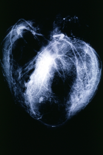
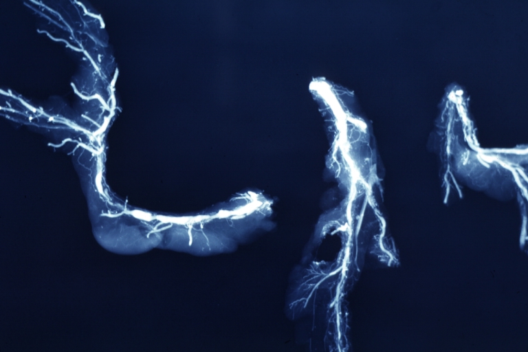
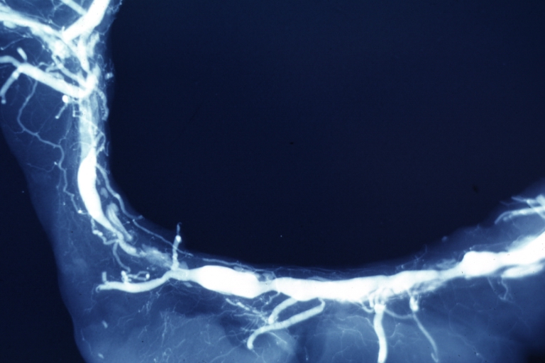
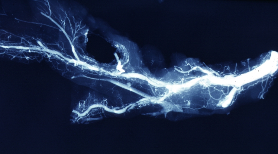
Postmortem Angiogram of Coronary Arteries
-
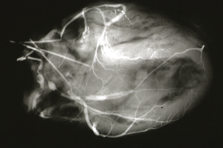
Myocardial Infarction: Postmortem angiogram of coronary arteries
-
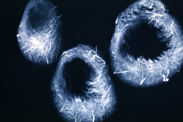
Angiogram: X-ray, horizontal sections of ventricle showing penetrating artery distribution (a quite good example)
-
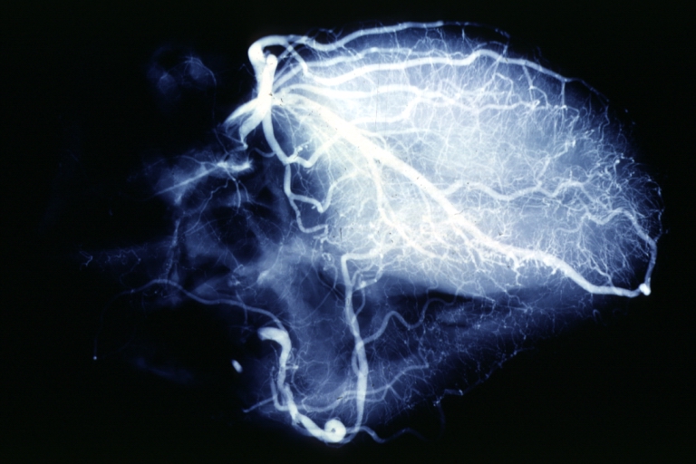
Angiogram: X-ray, postmortem coronary arteries with multiple lesions
-
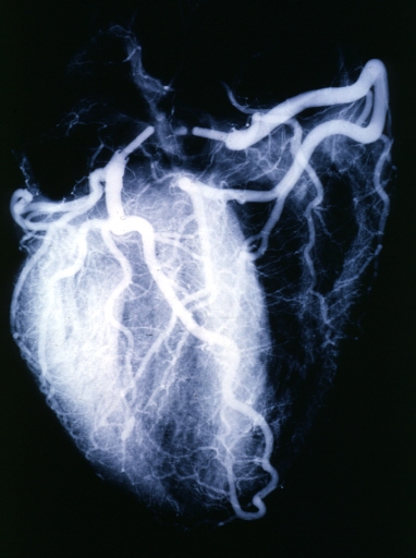
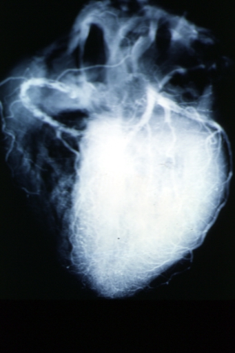
Angiogram: X-ray postmortem normal coronaries
-
Angiogram: Postmortem angiogram with apparent lesions in proximal right coronary artery
-
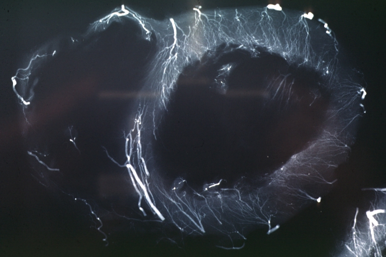
Angiogram: X-ray, postmortem injection horizontal slice of left ventricle showing very well penetrating arteries
-
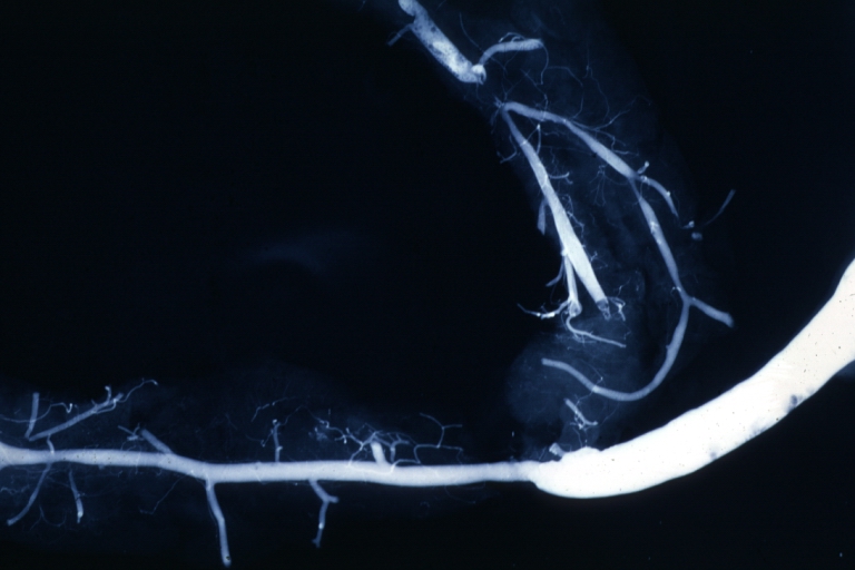
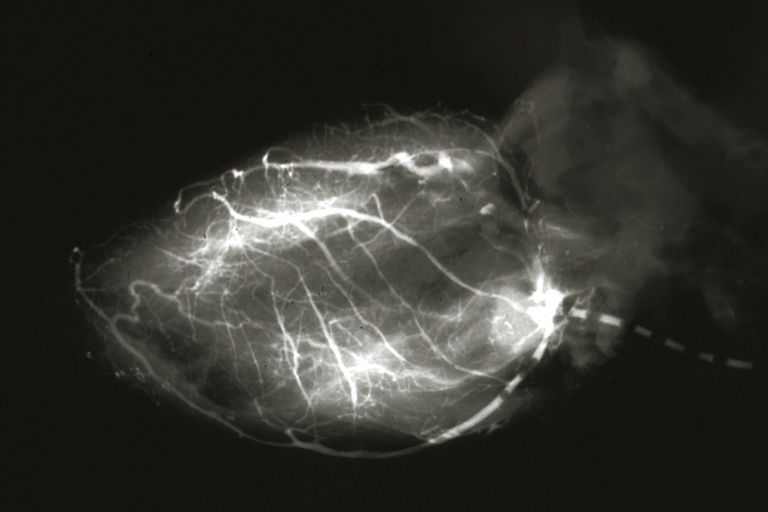
Angiogram Saphenous Vein Bypass Graft: X-ray shows rather close-up large vein anastomosing to much smaller artery
-
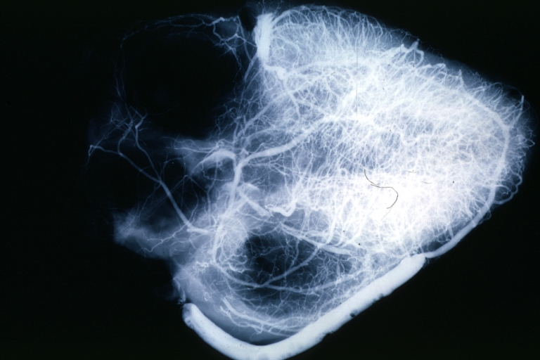
Angiogram Saphenous Vein Bypass Graft: X-ray postmortem injection showing vein anastomosis very well and the vasculature of the right and left ventricles
-
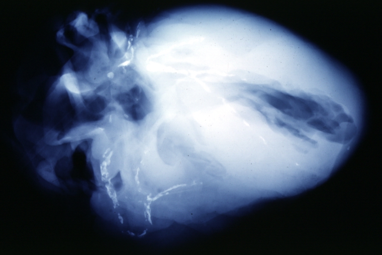
Coronary artery: Atherosclerosis: X-ray postmortem extensive lesions in this x-ray of whole heart
-
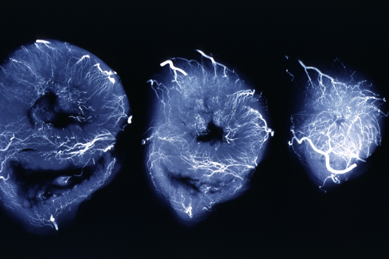
X-Ray Intramyocardial Arteries: X-ray three horizontal slices of ventricles showing quite well the penetrating arteries
-
X-Ray Intramyocardial Arteries: X-ray three horizontal slices of ventricles showing quite well the penetrating arteries
-
Coronary Artery Anomalous Origin; Left From Pulmonary Artery: Angiogram, postmortem, after switch of left coronary artery to aorta
-
Coronary artery: Atherosclerosis: X-ray, postmortem, dissected arteries and extensive lesions
-
Coronary artery: Atherosclerosis: X-ray, postmortem, close-up view of artery with extensive lesions (very good example)
-
Coronary artery: Atherosclerosis: X-ray, postmortem, dissected artery, lesions in small branches


Related Chapters
- Interventional cardiology
- Cardiology
- TIMI flow grade 0
- TIMI flow grade 1
- TIMI flow grade 2
- TIMI flow grade 3
- TIMI frame count (TFC)
- TIMI myocardial perfusion grade 0
- TIMI myocardial perfusion grade 1
- TIMI myocardial perfusion grade 2
- TIMI myocardial perfusion grade 3
- Thrombus Grading
- Complications during and following cardiac catheterization
- Access site complications
- Angiogram
- Suggested angiographic projections
- Congenital anomalies of the coronary circulation
- Anomalous origins of coronary arteries
- ST Elevation Myocardial Infarction Coronary Angiography
External links
- Cardiac Catheterization information from Children's Hospital Heart Center, Seattle.
- The MD TV: Comments on Hot Topics, State of the Art Presentations in Cardiovascular Medicine, Expert Reviews on Cardiovascular Research
- Clinical Trial Results: An up to dated resource of Cardiovascular Research
References
- ↑ Connolly JE. The development of coronary artery surgery: personal recollections. Tex Heart Inst J 2002;29:10-4. PMID 11995842.
- ↑ Proudfit WL, Shirey EK, Sones FM Jr. Selective cine coronary arteriography. Correlation with clinical findings in 1,000 patients. Circulation 1966;33:901-10. PMID 5942973.
- ↑ Sones FM, Shirey EK. Cine coronary arteriography. Mod Concepts Cardiovasc Dis 1962;31:735-8. PMID 13915182.
- ↑ Smith SC Jr, Feldman TE, Hirshfeld JW Jr, Jacobs AK, Kern MJ, King SB 3rd, Morrison DA, O'neill WW, Schaff HV, Whitlow PL, Williams DO, Antman EM, Smith SC Jr, Adams CD, Anderson JL, Faxon DP, Fuster V, Halperin JL, Hiratzka LF, Hunt SA, Jacobs AK, Nishimura R, Ornato JP, Page RL, Riegel B; American College of Cardiology/American Heart Association Task Force on Practice Guidelines; ACC/AHA/SCAI Writing Committee to Update the 2001 Guidelines for Percutaneous Coronary Intervention. ACC/AHA/SCAI 2005 Guideline Update for Percutaneous Coronary Intervention-Summary Article: A Report of the American College of Cardiology/American Heart Association Task Force on Practice Guidelines (ACC/AHA/SCAI Writing Committee to Update the 2001 Guidelines for Percutaneous Coronary Intervention). J Am Coll Cardiol. 2006 Jan 3;47(1):216-35. PMID 16386696
de:Koronarangiographie eu:Koronariografia nl:Hartkatheterisatie