Cantilever mechanics (orthodontics)
| Cantilever mechanics (orthodontics) |
Editor in Chief: Berna Zorkun DMD [1]
Overview
A cantilever is, in principle, any piece of wire, whose end is inserted, on one side, into a bracket or a tube, or included in the acrylic of a removable appliance, while the other one is tied to another unit, with only a one-point contact. When using the cantilever, the orthodontist can easily estimate the force system on both units, just measuring the length of the appliance and its force by means of a dynamometer -in the direction of its activation- and thereby predict the clinical result
Example of cantilever application in orthodontics
The cantilever may have many different configurations and uses in orthodontic therapy.
The cantilevers may be utilized in all the planes of space. They can be applied both buccally and lingually. Instead of a complete list, some examples are shown:
- Control of the labio-lingual position of the incisors and canines and the bucco-lingual position of the molars and premolars.
- Control of rotation of teeth with buccal cantilevers or palatal and lingual arches, used in a statically determinate way
- Vertical control, through extrusion or intrusion of lateral and anterior teeth.
- Generation of a third order control (torque) to the anterior as well of the buccal segment.
- Generation of molar or canine uprighting.
Within the individual segments, a large number of different applications is possible too.
Cantilever Force System
Considering the biomechanical force system generated by a cantilever, it is important to remember that a combination of a moment and a force is produced at the unit into which the cantilever is inserted, whereas only a single force is developed with respect to the point of force application of the other end. The magnitude of the two forces is equal and opposite, according to the third law of Newton, and the activation can be measured by a dynamometer.
The value of the moment is equal to the length of the cantilever multiplied by the force: M = F x d
An important characteristic of the force systems generated by the cantilever, is their high degree of constancy over time and deactivation. In other words, the forces at its two ends, maintain their direction and decrease in a linear manner, proportionally to the cantilever deactivation. In addition, there is also a high degree of constancy of the MOMENT/FORCE ratio (with respect to the bracket). This means also a homogeneous dental movement. The force system being always directed towards the treatment goal, this is rapidly achievable, with a minimum of round tripping and iatrogenic damage.
Cantilever Length and Load Deflection Ratio
On the basis of the previous statements, it is evident that cantilevers should be as long as possible, if their aim is to produce only a moment, while the force is less desirable. If, for example, a cantilever is used for the uprighting of a molar, which should not be extruded, the cantilever should be as long as possible or counteracted by a second cantilever.
The same applies to those cantilevers used for rotation, e.g. a cantilever which should not displace, but only rotate the canine.
If, on the contrary, the effect of the force is desirable and the moment less wanted, the cantilever should be kept short and its cross section dimension reduced, in order to keep the load/deflection rate low.
The load/deflection ratio delivered by a cantilever, should -as for all the active elements of the appliance- be as low as possible, leaving the force system with a high degree of constancy. This is another reason for generally keeping the cantilevers long. In those cases where the cantilevers, for different reasons are short, the load/deflection rate can be lowered by the addition of one or more loops, or by using a smaller wire dimension. The latter does, however, also cause a problem, as the play between wire and bracket (tube) may become unacceptable. In this case, a composite cantilever could be advisable.
A third and better solution is to choose a wire alloy with a lower stiffness. For this reason and for its high formability, cantilevers are usually made out of beta titanium.
Point of Application of the Force
A factor of extreme importance -when inserting a cantilever and determining its length- is the point of force application where the single point contact is made. The type of dental displacement which is produced, should be predicted on the basis of the force system, expressed as M/F ratio with respect to the Center of Resistance (CR), and not to the bracket. A single force, perpendicularly applied to the long axis of the tooth at the bracket, produces both a moment and a force with respect to the CR. If the moment has to be reduced, this can be obtained by displacing the point of force application closer to the CR, e.g. by means of a power arm.
Wire Selection
Wire selection, when making a cantilever, is principally determined by the length of the cantilever itself. Factors of importance are the load/deflection rate and the maximum elastic moment or yield moment. If a cantilever has to be short (e.g. 10 mm), it is important to use a wire with a low stiffness, i.e. high elasticity as beta titanium 0.018" round. This wire does, however, rotate in the bracket and can thus only be applied when welded to a stiffer, 0.017"x0.025" piece of wire. The yield moment (My) of this wire is 1450gm-mm, thus deforming permanently with 145gm of activation. If the cantilever had a double length (20 mm), its maximum activation would be 72.5gm.
In the case of a longer cantilever -e.g. 20 mm- it is advisable to use a wire with a more elevated My, as for example beta titanium 0.017"x0.025".A cantilever constructed with this wire can be loaded until 157gm, without a permanent deformation. Another possibility is to use stainless steel, which has an even higher My, but also a stiffness which is 2.5 times that of beta titanium . This means a very and often unacceptable high load/deflection rate. This latter can be reduced, by adding loops to the stainless steel appliance. The use of stainless steel as cantilevers is thus recommended, only in the case they are longer than 20 mm, if the desired force level is above 70-80gm.
Composite Cantilevers
Composite cantilevers are made out of two different wires which are joined together by a spot welding .
These cantilevers can be very useful since they offer the advantage of having different rigidities in different parts. Since beta titanium has the best joining properties most of the time composite cantilevers include a stiffer part beta titanium 0.017" x 0.025" and a more elastic part made out of beta titanium with round 0.018" section.
Composite cantilevers can be also created joining 0.018" wires to a beta titanium lingual arch or trans palatal arch.
Configuration
Another aspect to be considered, is the possibility to influence the force line of action, by altering the cantilever configuration.
The modification of the cantilever configuration will change the direction of the line of action of the resultant force. Depending on the desired force direction it is possible to add helices, or develop cantilevers with utility shape.
As a general rule the line of action of the force will be perpendicular to the structural axis of the wire when activated. Using different configurations a certain variation is, as seen above, possible. In the case of the curvature the activated wire will approximate the straight wire and therefore have a tendency to "curl" up shorten during deactivation. A tip-back bend will make a curvature during activation and straighten during deactivation.
Image Gallery
-
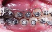 A cantilever is used to obtain the buccal displacement of tooth 1.4 which is in cross bite.
 -
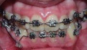 Cantilever attached to a power arm . The power arm is applied on the lateral incisor bracket, whereby the force, delivered by the cantilever, generates a M/F ratio at the bracket equal to the length of the power arm (if this is perpendicular to the line of action of the force).
 -
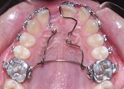 TwoComposite Cantilevers. Two cantilevers made out of beta titanium 0.018" are welded to a beta titanium transpalatal arch.


External Links