Intraventricular conduction delay anatomy and physiology
|
Intraventricular conduction delay Microchapters |
|
Differentiating Intraventricular conduction delay from other Disorders |
|---|
|
Diagnosis |
|
Treatment |
|
Case Studies |
|
Intraventricular conduction delay anatomy and physiology On the Web |
|
FDA on Intraventricular conduction delay anatomy and physiology |
|
CDC onIntraventricular conduction delay anatomy and physiology |
|
Intraventricular conduction delay anatomy and physiology in the news |
|
Blogs on Intraventricular conduction delay anatomy and physiology |
|
to Hospitals Treating Intraventricular conduction delay anatomy and physiology |
|
Risk calculators and risk factors for Intraventricular conduction delay anatomy and physiology |
Editor-In-Chief: C. Michael Gibson, M.S., M.D. [1]; Associate Editor(s)-in-Chief: Mugilan Poongkunran M.B.B.S [2]
Overview
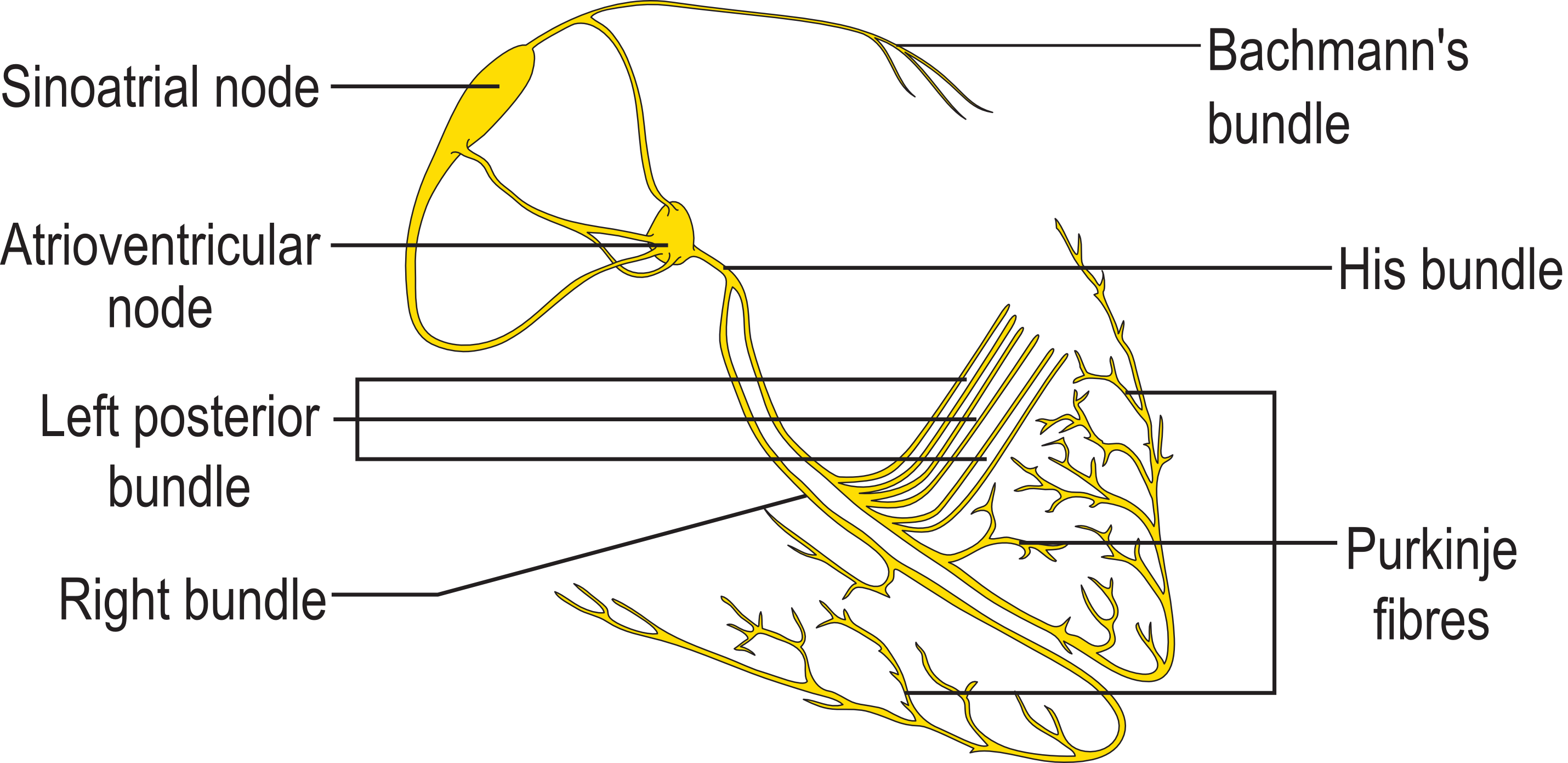
Intraventricular conduction delay are due to abnormalities in the specialized conduction system in the ventricles that transmit impulses arising from the SA node transmitted through the AV node to the ventricles. The normal intraventricular system starts at the AV node as bundle of His that divides into right and left bundle branches which after giving of the fascicular branches ends in the complex Purkinje system.
Anatomy and Physiology
Normal Anatomy
The conduction system of the heart consists of specialized cells designed to conduct electrical impulse faster than the surrounding myocardial cells. The intraventricular conduction system originates from AV node as bundle of His, branches and ends as the Purkinje system.
- The bundle of His divides at the junction of the fibrous and muscular boundaries of the intraventricular septum into the right bundle and left bundle.
- The left bundle branch penetrates the membranous portion of the interventricular septum under the aortic ring and divides into several smaller branches. Parts of the left bundle branch include a pre-divisional segment, anterior fascicle/hemibundle and posterior fascicle/hemibundle. Rarely a median fascicle is present in some hearts.
- The left anterior fascicle (LAF) supplies the anterior papillary muscle and the Purkinje network of the antero-lateral surface of the left ventricle.
- The left posterior fascicle (LPF) supplies the posterior papillary muscle and the Purkinje network of the postero-inferior surface of the left ventricle.
- The left median fascicle (LMF) runs to the interventricular septum. In most cases it arises from the LPF, less frequently from the LAF, or from both, and in a few cases it has an independent origin from the central part of the main left bundle at the site of its bifurcation.
- The right bundle is an anatomically compact unit that travels as the extension of the bundle of His after the origin of the left bundle. The right bundle branch courses down the right side of interventricular septum near the endocardium in its upper third, deeper in the muscular portion of the septum in the middle third, and then again near the endocardium in its lower third.
- The right bundle branch is a long, thin, discrete structure.
- It does not divide throughout most of its course, and it begins to ramify as it approaches the base of the right anterior papillary muscle, with fascicles going to the septal and free walls of the right ventricle.
- The Purkinje fibers connect the ends of the bundle branches to the ventricular myocardium. Purkinje fibers form interweaving networks on the endocardial surface of both ventricles and penetrate only the inner third of the endocardium, and they tend to be less concentrated at the base of the ventricle and at the papillary muscle tips.

Normal Physiology
Cardiac Action Potential
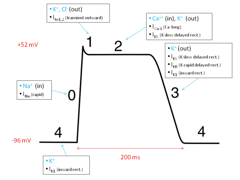
The standard model used to understand the cardiac action potential is the action potential of the ventricular myocyte. The action potential has 5 phases (numbered 0-4).
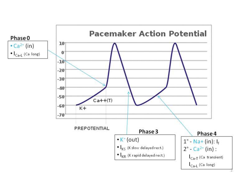
- Phase 4 : This is the resting membrane potential and describes the membrane potential when the cell is not being stimulated. The normal resting membrane potential in the ventricular myocardium is about -85 to -95 mV. All cardiac cells which belong to the excitatory system have an instable phase 4 i.e the pacemaker potential. Phase 4 is associated with heart diastole so is called diastolic depolarization.
- Phase 1 : This is the rapid depolarization phase. The slope of phase 0 represents the maximum rate of potential change and is known as dV/dtmax. Its behavior is different in contractile and pacemaker heart cells.
- Phase 2 : This "plateau" phase of the cardiac action potential is absent in pacemaker cells and it sustains muscle contraction.
- Phase 3 : This is the rapid repolarization phase of the action potential where the membrane potential is restored to about -80 to -85 mV.
- Refractory period : From the beginning of phase 0 until nearly the end of phase 2, each cell is in an absolute refractory period, during which it is impossible to evoke another action potential, followed, until phase 4, by a relative refractory period, during which a stronger-than-usual stimulus is required.
Conduction velocity of depends on the following factors :
- Rate of rise of phase 0 of the action potential (dV/dt)
- The height to which it rises (Vmax)
- The membrane potential at the time of stimulation : The more negative the membrane potential is, the more sodium (Na+) channels are available for activation, the greater the influx of Na+ into the cell during phase 0, and the greater the conduction velocity. Purkinje cells conduct rapidly, at 1 to 3 m/sec resulting in simultaneous depolarization and propagation of the cardiac impulse to the entire RV and LV endocardium.
Ventricular Depolarization and ECG

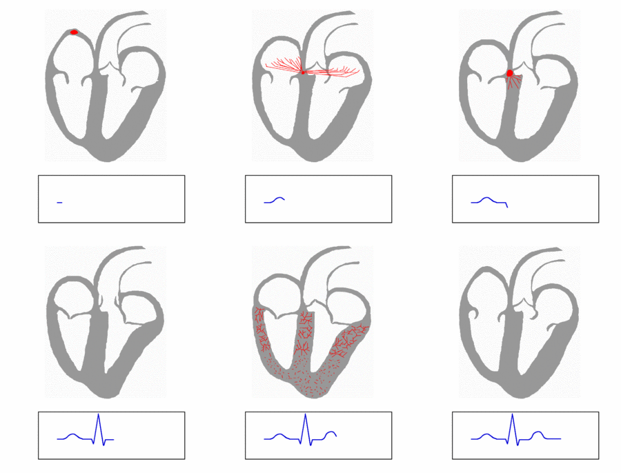
- First Phase : Normally the first part of the ventricles to be depolarized is the interventricular septum. The left side of the septum is stimulated first by a branch of the left bundle. It happens in the inital 30 milliseconds in QRS. On the normal ECG, this septal depolarization produces a septal q waves in leads I, aVL, and V6 and r waves in leads V1, V2, and aVR.
- Second Phase : Next phase is the simultaneous depolarization of the left and right ventricles usually gets completed in 40-60 milliseconds of QRS.
- Left ventricle activation : The left ventricle activation begins almost simultaneously at the insertion points of the fascicles of the left bundle branch. The left ventricle is normally electrically predominant and its activation is leftward and posterior due to its structural orientation producing deep S waves in the anterior precordial leads (V1 and V2) and tall R waves in the leftward leads (I, aVL, and V6).
- Right ventricle activation : The activation of the right ventricle starts at the origin of the right bundle branch.
- Ventricular repolarization : The last event of the cycle is the repolarization of the ventricles. It is the restoring of the resting state. In the ECG, repolarization includes the J wave, ST-segment, and T- and U-waves.[1][2]
- R wave peak time : It is the time for full depolarization of the ventricular free wall (from the endocardium to the epicardium) beneath any given ECG electrode and it corresponds to the interval from the beginning of the QRS complex to the time of initial downstroke of the R wave after it has peaked. In the right precordial leads, the upper limit of normal for R wave peak time is 35 milliseconds, whereas in the left precordial leads, it is 45 milliseconds.
References
- ↑ Gussak I, Bjerregaard P, Egan TM, Chaitman BR (1995). "ECG phenomenon called the J wave. History, pathophysiology, and clinical significance". J Electrocardiol. 28 (1): 49–58. PMID 7897337.
- ↑ OSBORN JJ (1953). "Experimental hypothermia; respiratory and blood pH changes in relation to cardiac function". Am J Physiol. 175 (3): 389–98. PMID 13114420.

